Homematic CCU3 Hub and RedMatic
- Add sensors to the control panel
- Creating system variables and programs
- Installing Node-RED
- Installation of an MQTT server
- Homematic -> INSTAR IP Camera
- INSTAR IP Camera -> Homematic
- Complete Node-RED Flow
Make your camera the heart of your smart home
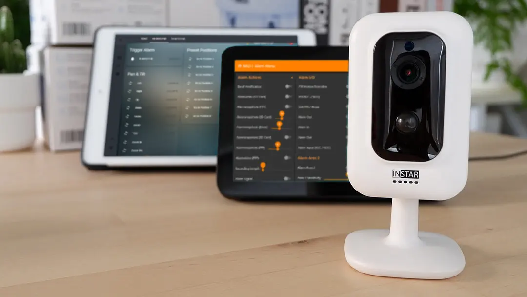
Using the MQTT interface of your INSTAR Full HD cameras you can connect them to an existing smarthome system (Home Assistant, OpenHAB, Node-RED, Athom Homey, Homematic, ioBroker, Loxone, homee) can be added. Or even make it the main broker for your MQTT sensors. MQTT allows you to automate ALL functions of your camera and link them to other services in your smarthome.
Control your camera via the IFTTT online service
On the IFTTT platform, we provided a service called INSTAR. The INSTAR applets provide you with the ability to control some settings of your INSTAR camera or INSTAR Cloud with IFTTT. You can connect INSTAR with triggers for location (Geo Location) and date & time, send notifications and much more. For example, you can connect INSTAR applets to the IFTTT location service and automatically disable the alarm when you arrive home. You can also use the INSTAR applets to create your own automation and connect them to other third-party applets.
Add sensors to the control panel
In order to be able to control your INSTAR IP camera with Homematic sensors both have to be integrated via the Homematic WebUI. To do this, proceed as follows:
- Start the WebUI user interface inside your web browser.
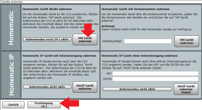
- Click on the "Teach in devices" button in the upper right area of the browser window.
- Activate the appropriate teach-in mode for the device that you want to add. More information can be found in the respective operating manual.
- Wait for the teach-in process to complete. To confirm the successful teach-in process, the LED of the device lights up green. If the LED is red, try again.
- After a short while, the newly trained device appears in the inbox of your WebUI.
Creating system variables and programs
In order to communicate with our sensors - in order to install the Homematic Funk-Bewegungsmelder, außen and trigger a system alert on motion, we need to create a system variable:
Click on New below to create a new variable:
Enter the following here to create a system variable named PIR Sensor, then click on Ok and in the following list click on Programs:
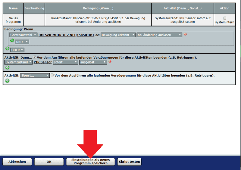
In the following window click on New again - here we can now configure and confirm the following program:
If we now trigger a motion detection, we will receive an alarm message:
Installing Node-RED
We have already worked with Node-RED and in conjunction with the MQTT protocol automated our IP Camera. Node-RED is very easy to install on the Homematic control panel using the RedMatic addon.
RedMatic combines several software components into one CCU add-on, a software package that can be conveniently installed on a Homematic CCU3 as additional software via the WebUI.
The Node-RED version installed comes with the CCU nodes for Node-RED, making it possible to implement rules, automation's, scripts and connections of external services and systems for a homematic system in a simple, visual way - and this largely without any programming knowledge.
The visualization and control includes RedMatic WebApp and Node-RED Dashboard. RedMatic WebApp is a user interface that can be used immediately without further configuration.
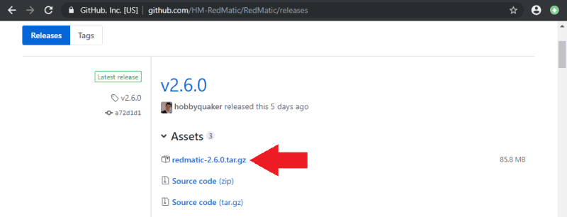
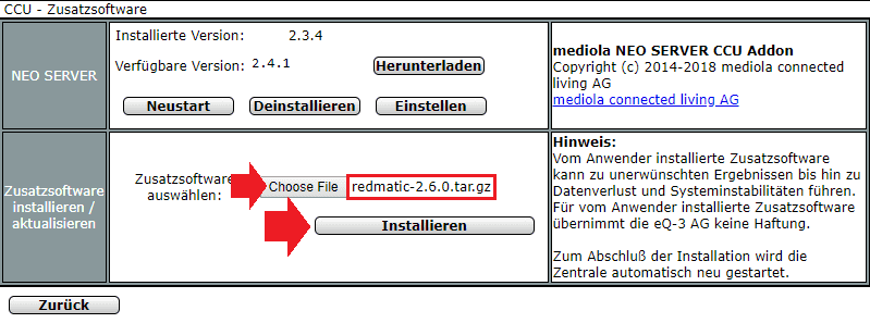
- First, we need to download the latest version from Github. You need the file
redmatic-<version>.tar.gz:
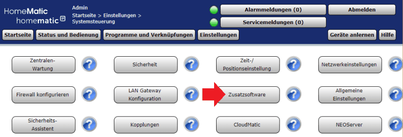
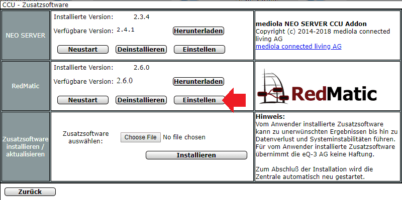
- In the Homematic WebUI, go to Control Panel Add-on Software:
- Select and install the downloaded file (can take up to 10min):
- Then wait until the CCU restarts - patience is required. The installation of RedMatic takes some time. Node-RED will be reachable under
http://<ccu-adresse>/addons/red. And the Node-RED Dashboard underhttp://<ccu-adresse>/addons/red/ui:
The default login is Admin (with a capital A) and the admin password on your CCU3!
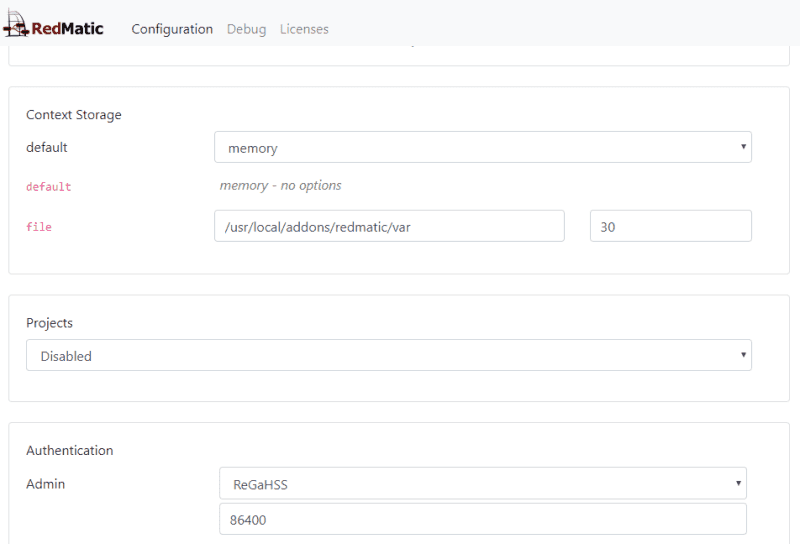
You can also manually set the password under Control Panel / Additional Software - change the authentication from ReGaHSS to Credentials:
Installation of an MQTT server
MQTT is a communication protocol developed specifically for IoT devices offering some benefits over regular _HTTP__ communication. However, it is a bit complicated to set up under Windows or a Raspberry Pi, as it requires an extra MQTT server. Fortunately, this is just as easy with the homematic center as the installation of Node-RED.
Nevertheless, the use of the MQTT protocol is purely optional. For the examples we will give below it is not needed (you can also replace the used MQTT nodes with link nodes and get the same result!). MQTT becomes important the moment you have another home automation systems, e.g. OpenHAB or ioBroker or want to use thirdparty sensors, which can not be integrated directly into Homematic. MQTT, in conjunction with Node-RED, can be the link that brings together all the building blocks of your automation.
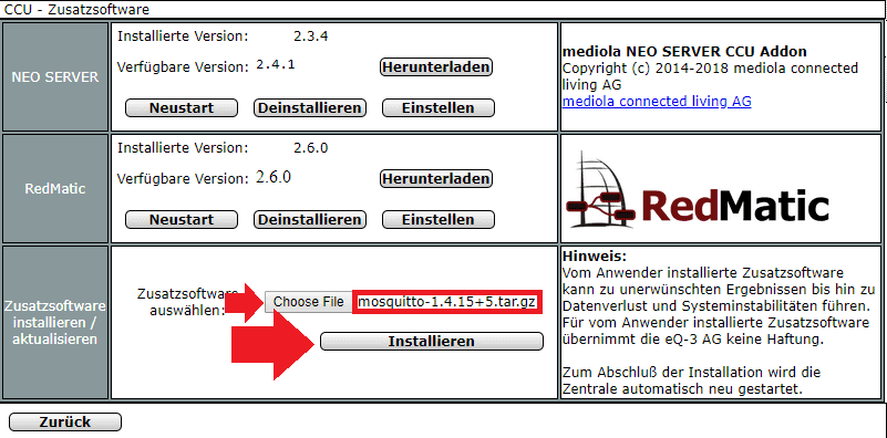
In order to use the MQTT protocol with the Homematic, we have to use the Mosquitto server addon for the Homematic CCU3. Go to the Release page on Github and download the latest mosquitto- <version> .tar.gz file there. You can then install it under System Control / Additional Software in the WebUI of the CCU3:
Enabling SSH Access (Optional)
By default Mosquitto listens on the ports 1883/mqtt and 1884/ws. If a certificate is available on the CCU, TLS listener will also be automatically opened (8883/mqtts and 8884/wss).
In addition to the broker, the addon also installs the command line tools mosquitto_pub and mosquitto_sub and links them to them /usr/local/bin/.
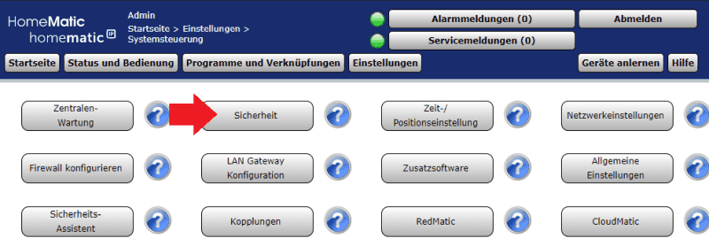
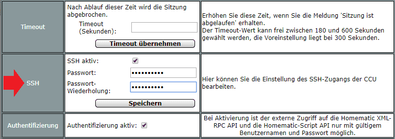
To enable SSH access, go to System Control / Security, activate the service and enter a password. Afterwards the CCU3 has to be restarted:
After rebooting, you can open your terminal - under Windows the free Terminus can be used - to log in to the IP address of your CCU with the user name root and the above set password:
The Mosquitto configuration can be found under /usr/local/addons/mosquitto/etc/conf.d/*.conf. To restart type /etc/config/rc.d/mosquitto restart.
When calling mosquitto_pub via CUxD Exec, the call must be preceded by the setting of the lib path, e.g.: LD_LIBRARY_PATH=/usr/local/lib /usr/local/bin/mosquitto_pub -t 'test' -m 'test'
Testing the MQTT server
The SSH access (above) allows the MQTT server to be tested directly on the operating system of the CCU3. In this section we want to connect to the server from a Windows computer. To do this we can use the tool MQTT.fx on Windows 10.
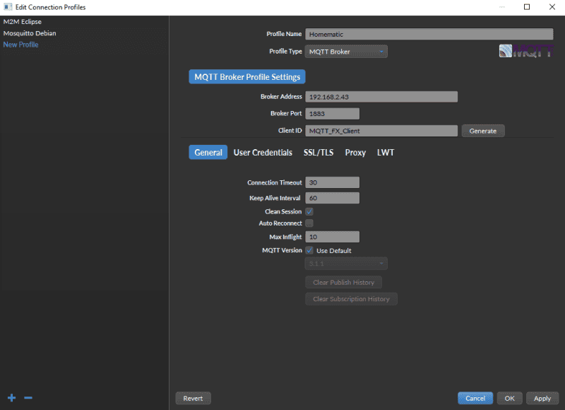
In the user interface, click the gear to add the configuration for the MQTT server to the Homematic CCU:
Enter the IP address of your Homematic control center as Broker Address and keep the port. If you changed the port via SSH or added user authentication in the previous step, you must consider this here:
Confirm the entries and click Connect next to the gear from the previous step. After that, switch to the Subscribe tab underneath, enter a # in the lines next to the Subscribe button and then click the button to subscribe to all MQTT messages that our server receives.
Then go to the Publish tab and enter MQTT Topic - e.g. /test/ - one and below a value - {"val":"1"} - which you want to publish under the topic:
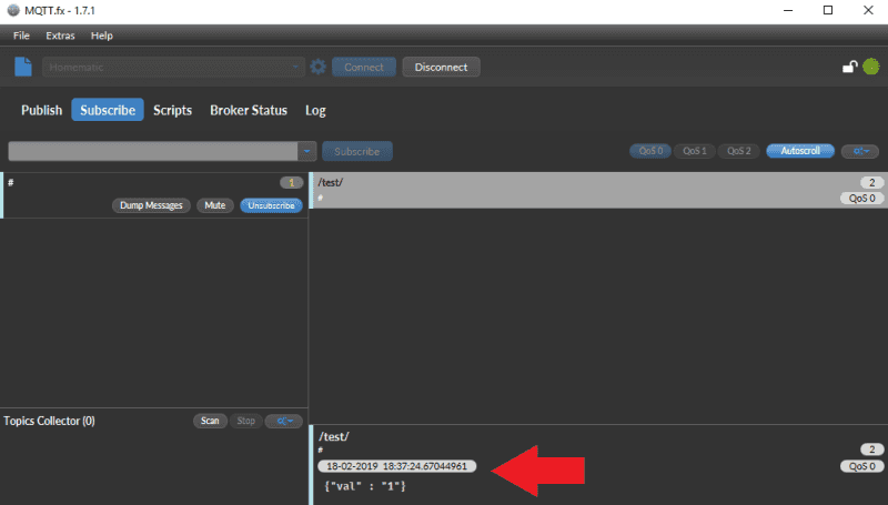
Once you clicked the Publish button go back to the Subscribe Tab, the message should be received from our MQTT server and sent back to MQTT.fx, as we indicated we wanted to be notified about all messages:
If you see this message, the server has been setup correctly and is active on your network.
Homematic -> INSTAR IP Camera
Now we have made all the preparations to integrate our INSTAR IP camera into the Homematic system. And this can now happen completely over Node-RED, which is much more flexible than the software the Homematic CCU provides. For this we can use the following tutorials, in which we had already carried out this integration:
We can actually recycle them completely with a small supplement, we will use the already pre-installed CCU nodes to query the status of our sensors at the Homematic central. However, the following Node RED flows use a special node named node-red-contrib-string that is not preinstalled in Node-RED. You can install it via the Palette menu.
Homematic Sensors (Motion Detector)
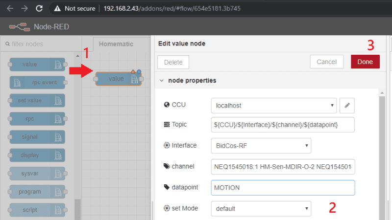
- We start by dragging a CCU Value Node onto the workspace and double-clicking on it to open the configuration page.
- Select BidCos-RF as an interface to embed your Homematic PIR motion detector.
- If you click in the Channel field, you will see all RF devices connected to your Homematic center. When we trained our motion detector to the control panel, we saw that the name of the detector begins with NEQ1545018. We have two entries at our disposal - the first ends at :0 and the second at :1. We'll pick the second one here (if you take the first one and you'll see that there are other variables available, including LOWBAT, which includes a low battery warning that we could include in our Node-RED flows.)
- As data point we choose Motion. This will always give us a message payload of
trueonce the sensor has detected a movement.
Now we will always receive a message in Node-RED for motion detections and need to respond to it. We can do this with the following flow, which you can copy and import into Node-RED (this flow includes the configuration of my motion detector - this you have to replace with your newly created one):
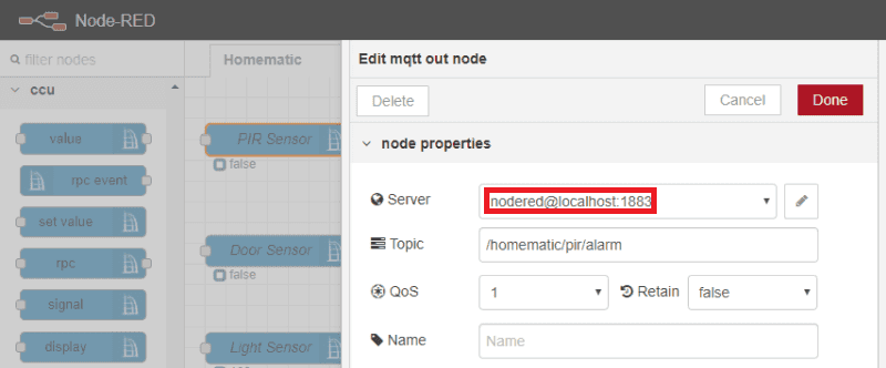
The output node on the right is an MQTT transmitter. Please make sure that this server is registered to localhost: 1883 - this is the MQTT server we have installed before.
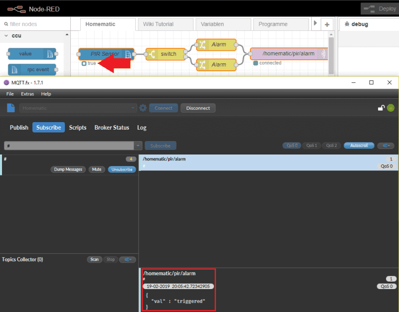
When you click on the red Deploy button and then trigger an alarm on your motion detector, you should see the message {"val":"triggered"} on the MQTT topic /homematic/pir/alarm in MQTT.fx.
INSTAR IP Camera
Now we have to implement this motion message so that it triggers an alarm in our camera. For this we can reuse a flow from one of the previous Node-RED tutorials:
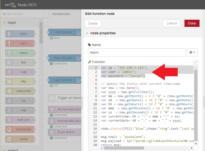
Note that you must edit the node marked above and enter the IP address and administrator login of your INSTAR FullHD camera (the command to manually trigger the alarm - /param.cgi?cmd=pushhostalarm - is only available on Full HD Camera Models. However, if you are using an HD or VGA camera model, you can substitute the CGI command in the flow with another that can be used with your camera model):
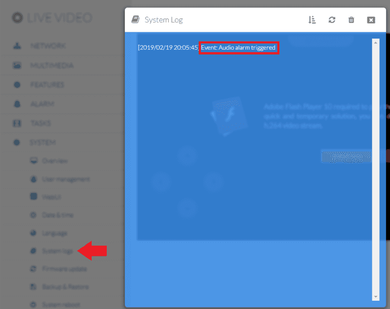
If you now trigger motion detection on your Homematic motion detector, you will find an Audio Alarm in the System Logbook in your camera's WebUI - this will trigger all alarm actions that you have activated in the WebUI of your camera - e.g. an alarm recording on the internal SD card or sending an alarm email.
Homematic Sensors (Door Sensor)
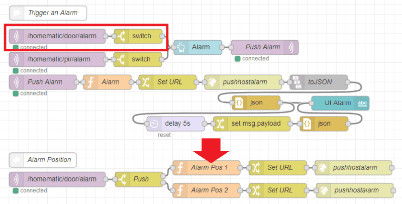
As a second example we can add the Homematic Funk-Tür/Fensterkontakt, optisch to let our camera pan towards the door as soon as it opens. The integration of the sensor into the homematic software and in Node-RED is identical to the previous example (the complete Node-RED Flow can be copied and pasted into Node-RED from the bottom of this page):
In the following part you can see that we have paired the door sensor with our Push alarm. Thus, both the PIR motion detector and the door sensor can trigger an alarm on the camera. Furthermore, a sequence was added to, when opening the door, pan our Full HD PTZ camera (e.g. IN-8015 Full HD or IN-9020 Full HD) in the direction of the door (this position must be stored in the WebUI camera under position 1: /param.cgi?cmd=preset&-act=goto&-number=0) and when closing the door the camera returns to the idle position ( stored in position 2: /param.cgi?cmd=preset&-act=goto&-number=1). For this to work, you must enter the IP address and the login of your camera in the two nodes under the red arrow (just as before):
INSTAR IP Camera -> Homematic
Creating the system variables
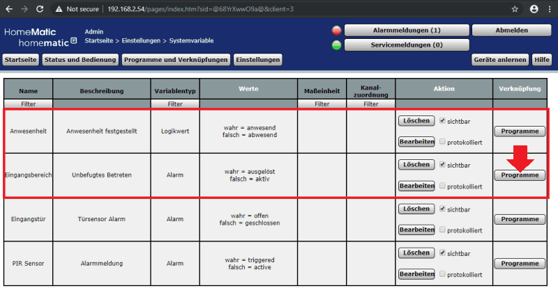
So far we have controlled the camera via the Homematic Control Center using Homematic sensors to trigger actions on the camera. The reverse case can be realized via the alarm server on the camera. In the following we want to use the System Variable: Anwesenheit - which represents a logic value by type and in which Homematic is pre-defined - in the Homematic control center to switch a self-created alarm variable (Eingangsbereich).
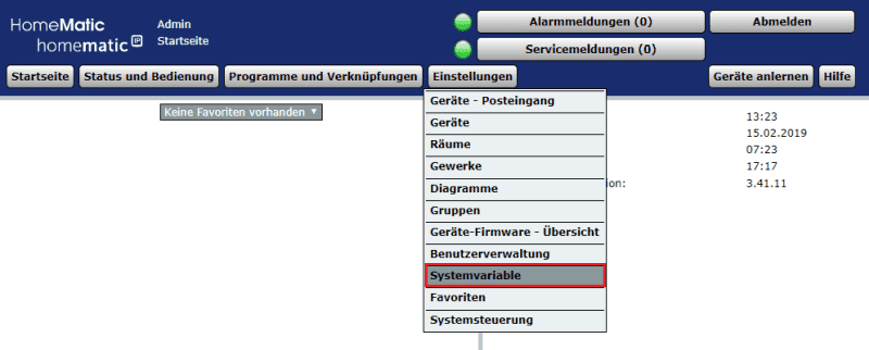
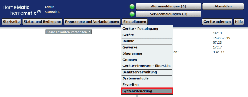
These variables can be created as follows under Einstellungen > Systemvariable:
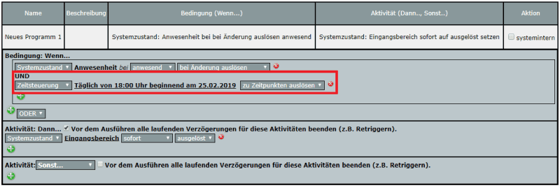
To link these variables, we have to click on the Programs button - marked with a red arrow at the top of the image - and create the following program:
This program pays attention when the system status Anwesenheit is switched to anwesend and in this case switches the system status Eingangsbereich area to triggered.
Or to put it simply, if our camera detects a person (via the internal motion detector or motion/audio detection), the Homematic Control Center should be notified of the presence of a person and an alarm triggered for the entrance area.
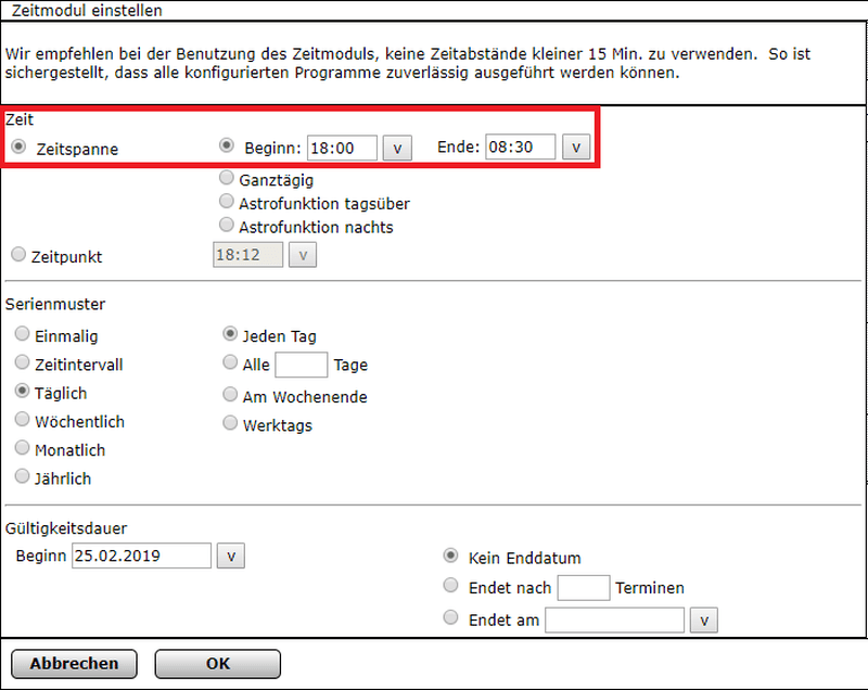
It makes sense to define a time window in which this rule should be active by clicking UND on the green +, selecting Zeitsteuerung and then selecting a time window in the Zeitmodul:
The example specifies that the alarm is only triggered when the camera detects motion between 18:00 and 8:30 hours.
Configuration of Node-RED
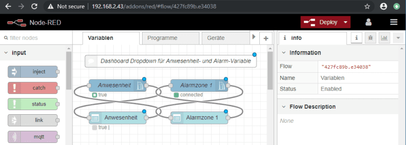
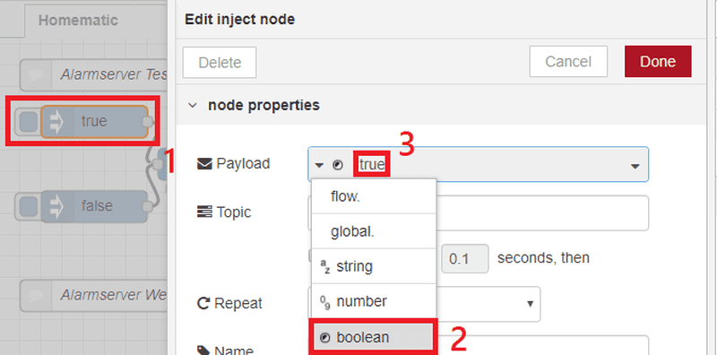
We can now take a sysvar node in Node-RED and feed it via two Inject nodes with the Boolean true or false.
Shown above is the configuration of the True Inject node - for the second one false must be selected.
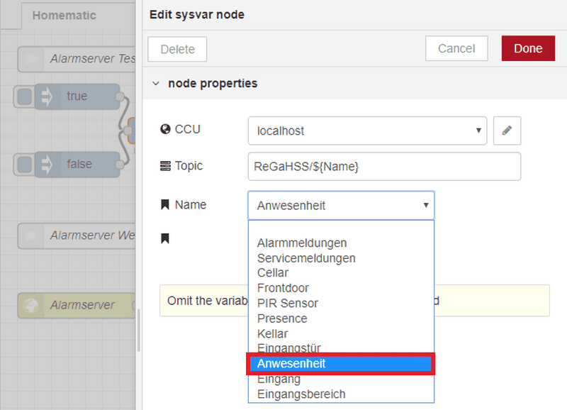
In the sysvar node we can select our presence system variable here:
If we now click on our true and false nodes, the system variable Presence in the Homematic central will be set to true or false. In the picture below we have placed a debug node at the end of the sequence which gives us a text output on the right side - so we can see exactly what has just been sent to the CCU:
Since we have coupled the system variable Anwesenheit with our alarm variable Eingangsbereich via program, we now also see a system alarm in the Homematic every time we click on the true Inject Knoten:
In an earlier tutorial we had already created a webhook in Node-RED that we can use as an alarm server to trigger a Node-RED sequence with our camera. We can recycle this code here - in simplified form:
This sequence provides an HTTP inbound node that, when the camera contacts the alarm server, sends an HTML page in response. In the node you can see that this node builds a Webhook based on the URL alarm/eingang - note however that this URL is relative to the address of Node-RED. The full path to access the Webhook was //addons/red/alarm/eingang:
When this message shows up we use a change node to send a true to the presence of sysvar node - just like we did manually above via the inject node. Below we have another delay node which automatically sets the status back to false after 5s and thus activates the alarm again.
Alarm server setting on the camera
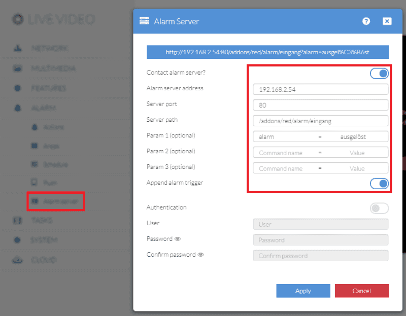
Now we have to set up the alarm server connection in our camera. The whole thing should look like this:
The address of our alarm server is the local IP address of the CCU, the port is 80 and the server path is /addons/red/alarm/In. The parameter below is optional and is only used for the web page that our webhook provides. In the WebUI of the camera it has also been activated that the alarm trigger should be attached as well - if, for example, you only use the internal PIR sensor of your camera for motion detection, an &active=5 will be attached to the URL (which number stands for which trigger can be found here). You can test the URL by calling the address in your web browser http://<IP Adresse der CCU>/addons/red/alarm/eingang?alarm=ausgelöst&active=5:
Calling this URL simulates the triggering of the alarm server by the camera. We should expect to see an alarm in the CCU:
Every time the camera now triggers an alarm and contacts the alarm server, the presence of a person is now registered in the Homematic control centre and an alarm is triggered immediately outside working hours from 18:00 to 8:30 - please note, however, that this function has a cooldown of 60s on the camera - so an alarm can only be triggered a maximum of 1 time per minute! You can now link this alarm to any variable in your home automation system and thus automate reactions to intrusion.

