Wiring Connector
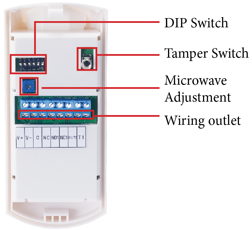
| V+ | Power Supply + | Connector for the 12V power supply + |
| V- | Power Supply - | Connector for the 12V power supply - |
| C & NC | Relay Jumper NC | Allows you to set the relay to Normally Closed (C&NC). In NC mode an interruption in the connection to the sensor, e.g. when it is damaged, will lead to an alarm. N.C. is the standard mode. |
| C1/T2 & NO1 | Relay Jumper NO | Allows you to set the relay to Normally Open (C1/T2 & NO1). In NO mode an interruption in the connection to the sensor will not cause an alarm. The N.O. mode is not recommended. |
| C1/T2 & T1 | Tamper Switch | This is for external tamper switch to cause an alarm in case the sensor is opened to avoid manipulation. |
Connect the IN-Motion 500 with your INSTAR Camera
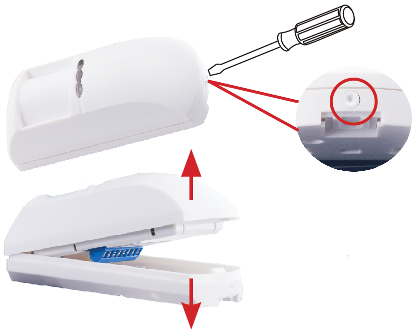
Step 1: Open the IN-MOTION 500 by using a Philips screw driver to press the button at the bottom. Separate the front cover from the back cover.
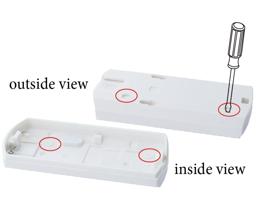
Step 2: Use the screwdriver to push one of the two holes, AND then induce the 4-wires of the 5 meter cable into this hole and proceed to next step.
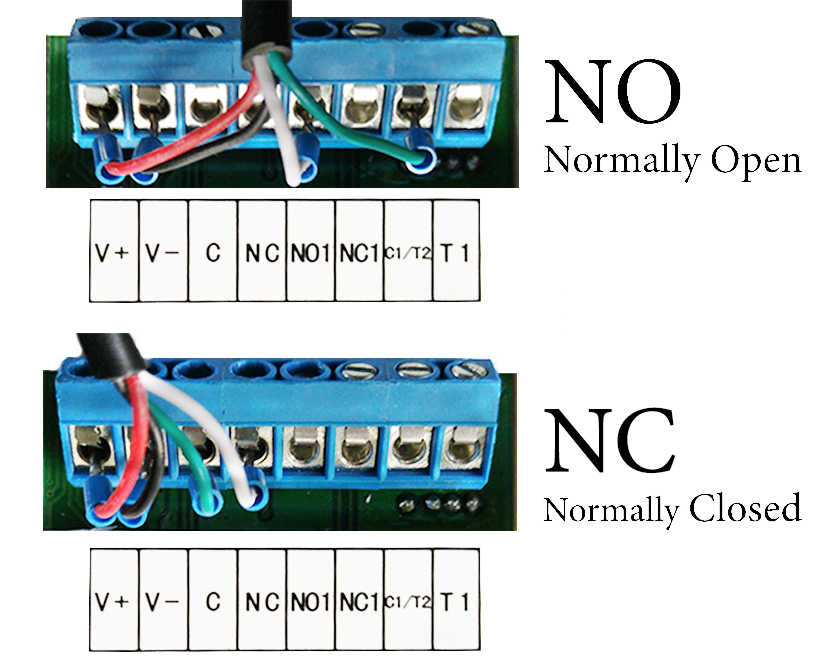
Step 3: Loosen the screws of V+, V-, C and NC (or C1/T2 and NO1) and insert the red wire to V+, the black to V- and the two signal cables to NC or NO ports.
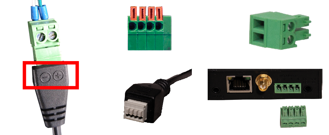
Step 4: Tighten the screws and close the casing. Clip the casing to the bracket. Connect the power plug to the delivered 12V/1A power supply. Connect the two signal wires to the cameras alarm input I/O. The connector for the alarm input of your camera might look different depending on your camera model. Please refer to your IP Camera user manual to identify the correct I/O ports. You may choose either polarity when connecting the cable.
Technical Specifications
| Sensor Model | INSTAR IN-Motion 500 Dual Microwave & PIR Motion Detector |
|---|---|
| Operating Voltage | D.C. 12V |
| Current Consumption | 62mA @ DC12V |
| Relay output | NC / NO, DC 25V / 100mA |
| Detection Angle | 110° |
| Detection Area | 12 m x 12 m |
| Start-up Time | 60 seconds (warm-up time up to 10 minutes in temperatures below -10°C !) |
| RF Interference Compensation | 10MHz 1GHz 20V/m |
| Alarm Indicator | Red and Blue LED |
| Alarm Output | N.C. or N.O., DC 25 V / 100 mA |
| Tamper Output | N.C., DC 25 V / 100 mA |
| Sensor | Dual element pyroelectric and microwave sensor |
| Environment Humidity | 95% RH (no congelation) |
| Working Temperature | -10°C to +50°C |
| Installation Mode | Wall mount |
| Mounting Options | Ceiling- or wallmount |
| Size (H/W/D) | 60 mm / 45mm / 136 mm |
| Weight | 150g |
| Compatible with | IN-2905 V2, IN-2907, IN-2908, IN-3001, IN-3005, IN-3010, IN-3010 PoE, IN-3011, IN-4009, IN-4010, IN-4011, IN-5907HD, IN-5907HD PoE, IN-6011HD, IN-6012HD, IN-6012HD PoE, IN-7011HD, IN-7011HD PoE |
